
2 EMS Sites to Serve You.
We offer electronic manufacturing services in 2 buildings.
Building 1
Our first building (building 1) is located at 101 Electronics Bvld. We began offering contract manufacturing services there 1995.
Building 2
We eventually outgrew our first building. We built a 2nd manufacturing site (building 2) in 2012,
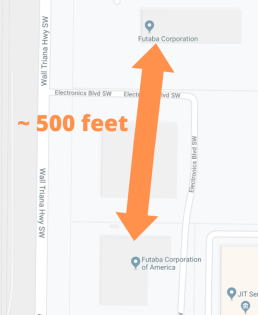
The distance between the two buildings is less than 500 feet away. Both sites are in operation.
Due to the close proximity of the two buildings, resources can be quickly moved between the two, if necessary.
Planning for Growth: We can grow with you!
Due to anticipating continued growth, we purchased the property adjacent to our 2nd building. We also designed building 2 in such a way that it can be connected to the new construction, thereby creating a single building that has double the capacity.
Capabilities per building
| Building 1 | Building 2 | |
| Address | 101 Electronics Blvd. Huntsville, AL 35824 |
2681 Wall Triana Hwy Huntsville, AL 35824 |
| Size | 45,000 sq. ft. | 51,000 sq. ft. |
| Current Layout | (3) SMT Lines (6) Cell Lines (11) Selective Solder Machines Silicone and Acrylic Conformal Coating Full ESD Floor |
(2) SMT Line – Room for (3) additional (0) Cell Lines (5) Selective Solder Machines No Conformal Coating Full ESD Floor |
| RoHS | Yes | Yes |
The rest of this page will dive into details of our PCB assembly capabilities.
SMT Capabilities
SPI Machines
We have SPI (Solder Paste Inspection) machines placed at the beginning of our production lines – right after the solder paste screen printers. With the increased density of today’s printed circuit board assemblies, combined with the ever-miniaturization of electrical components, having a consistent and accurate screen printing of solder paste onto a PCB has become a critical component in successfully manufacturing boards with small devices.
SMT Machines
The SMT machines pick components from reels and place them into the solder paste that was screen-printed on the PCB. These machines are frequently called “pick and place” machines.
All of our SMT pick-and-place machines are made by Panasonic. We decided to use Panasonic SMT machines long ago and have continued to stick with them due to their outstanding support and superior spare parts inventory.
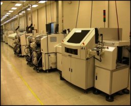
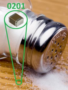
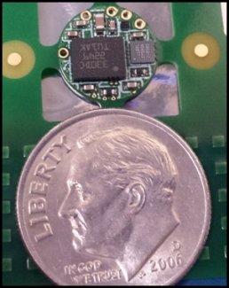
Our SMT machines are capable of placing components from the tiny “0201” package size (0.024” x 0.01”) to a very large component that is 2.3” x 2.3”.
To put into perspective how small an “0201” package is, one side of it measures 0.01”- the same dimension as an edge on your average grain of table salt!
The machines are also capable of placing BGA devices that have a lead pitch down to 0.4mm.
Nitrogen Reflow Oven
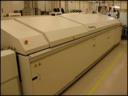
Oven Temperature Profile
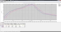
Reflow – What is it?
Our SMT lines have nitrogen reflow ovens. After the SMT machines pick and place all the components into the solder paste, the populated board moves into a reflow oven. Here the solder paste is carefully melted to the point where the electrical devices make electrical connection with the PCB. The reflow oven has several controlled temperature zones within it that result in an optimally soldered circuit board.
Nitrogen Reflow improves quality
A key factor in our high quality is the use of nitrogen reflow ovens. When oxygen is present during reflow, there is a much higher risk that the components will oxidize. At best, oxidation hinders electrical conductivity; at worst, it causes solder not to adhere to the components.
Nitrogen Reflow: how it works
Nitrogen reflow ovens work by pumping the heating chamber with nitrogen. Since nitrogen is lighter than oxygen, oxygen is pushed down to the bottom of the chamber, away from the circuit boards. This reduces the exposure of the boards to oxygen during the reflow process, resulting in high-quality solder joints.
Nitrogen reflow decreases process times
A side benefit of using nitrogen reflow is that the reflow process is faster than when not using nitrogen. This decrease in process time means higher productivity, resulting in lower manufacturing costs. Lower manufacturing costs means we can offer lower prices to our EMS customers.
SMT AOI
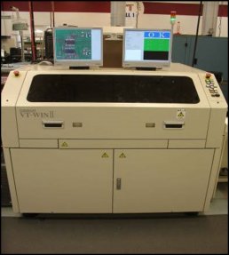
Component and solder inspection
AOI stands for “Automated optical inspection”. AOI is an automated visual inspection of a printed circuit board assembly. Our SMT AOI machines are placed after the reflow ovens. The AOI machines verify not only that the SMT machines placed parts on the board correctly, they also check the soldering condition of the device to the PCB. These machines help us maintain high quality levels for our EMS customers.
Traceability
We place with our SMT machines a small 5mm x 5mm 2D barcode on every board that we manufacture. This barcode contains simply a unique, sequential 10-digit number that is never repeated. Besides just inspecting for parts and their soldering condition, the AOI machines scan this 2D label. We then extract the AOI inspection results and link it to the scanned in serial number.
All of our AOI machines store inspection results in our manufacturing database that we call the “Tracking System”. Our Tracking System has been recording SMT AOI inspection results in real-time for every single unit that we have produced since 2006.
This data is accessible to our employees via our internal website. By having this data online, various departments can look for trends in the data and take appropriate action, where necessary.
Post-SMT Capabilities
What happens to the board after SMT depends on the printed circuit board assembly’s design and customer requirements.
Handload
Parts that cannot be placed automatically with our SMT equipment must be hand-placed/handloaded.
There are 2 methods of soldering handloaded parts: pin-in-paste and selective soldering.
Pin-in-paste
Just after the SMT process, but before the solder reflow oven, an operator can hand-place devices into the solder paste that is on the PCB. When the circuit board goes into the nitrogen reflow over, the handloaded part is then soldered to the board.
Selective Soldering
Futaba has numerous (15) selective soldering machines. These are robotically-controlled machines that move around a nozzle of molten solder. The nozzle comes into contact with the leads of the handloaded devices needing to be soldered to the PCB. These machines use vision systems to precisely locate the area to be soldered.
Handload Verification
Anytime a human is required to place a part on a circuit board, there is the risk that the part can be placed incorrectly. We have 3 ways to virtually eliminate the possibility that our customers will receive a board from us with an incorrectly handloaded part. The 3 ways are:
• Excellent employees
We minimize the risk by hiring trained and experienced employees.
• Use of jigs.
Use of jigs made by our Process Engineering group that prevents the operators from inserting certain components incorrectly (such as backwards).
• Automated Optical Inspection (AOI)
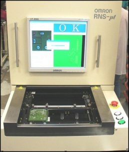
Like the SMT AOI explain above, we have several handload AOI systems that confirm that the handloaded parts were soldered correctly. These systems are also linked to our Tracking System database in order to store a unit’s inspection results.
Depanel
Individual circuit boards are normally connected together (i.e. “panelized”) during the SMT process. After SMT the units are separated by “depanelling” them.
“Pizza-cutter” depanelling
In the past (but still practiced by many EMS companies), boards were depanelled by the use of a rotary cuter. This process is very similar to cutting a pizza into slices. This old-school method potentially damages boards by putting strain on them, potentially resulting in cracked capacitors.
Router-based depanelling
Futaba avoids the potential quality issues from using rotary blade-based depanellers by using a different method. Futaba uses a robotically-controlled, high speed routing bit to cut away parts of the panel that need separating. This method puts no strain on the assembled boards.
In-Circuit Testers (ICT)
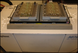
An In-circuit tester is frequently called a “bed-of-nails tester”. These testers use a high volume of probe pins to check the functionality and/or value of individual devices on the printed circuit board assembly.
Thanks to Futaba’s use of barcode scanning in our warehouse and at the SMT machines, we are extremely confident that we place the correct parts on a customer’s PCB. Yet, some customers – especially those in the medical and automotive industry – would like the added assurance that correct parts are used by requiring us to perform in-circuit testing.
Conformal Coating (CC)
Some of our customers that we provide EMS services for have their circuit boards placed in harsh environments – such as in a location of high-humidity, temperature extremes, or contaminated air. To protect their circuit boards from this harsh environment, they want us to spray/apply conformal coating on their boards. Conformal coating (frequently called “CC”) is a thin protective coating that ‘conforms’ to the circuit board’s devices and PCB.
Futaba has 2 types of conformal coating machines: silicone and acrylic.
Miscellaneous Processes
Epoxy, RTV
The fewer manufacturing steps needed to produce a printed circuit board assembly, the lower the manufacturing costs will be. So, the more handload parts that can be replaced with SMT ones, the better. Due to the nature of the application, there are some miscellaneous steps that are sometimes needed. For example, we have a customer that must have very large capacitors placed on their boards, and the end use of their product is in an environment where the unit will experience a lot of vibration. To better secure these large capacitors to the board, epoxy or RTV is applied to these devices. This added “glue” will help prevent the capacitor from breaking off during extreme vibration.
End of Line Testing (EOLT)
Nearly all of the assemblies we manufacture undergo an electrical functional test after the unit has been fully assembled. Obviously, the place where a unit has completed its assembly process is at the end of the manufacturing line –hence the term, “End of Line” testing. End of Line Testing is also called “Functional Testing”.
Here test equipment applies power to the board, sends signals, measures voltages and currents, communicates with the board, etc. The purpose of this test is to see if the unit behaves (i.e. functions) correctly. All of our EOL testers store their test data into our Tracking System database that was mentioned earlier.
Futaba has a Test Engineering group that is responsible for designing and programming our test equipment. For details on the capabilities of our Test Engineering group, click here.
For more info on function testing at Futaba click here.
Packout
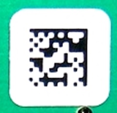
At the end of our process is a step that we call “Packout”. Here the operator scans the ultra-small (5mm x 5mm) barcode that is on the printed circuit board assembly. Our Packout software then confirms that all of the manufacturing steps required for the particular assembly passed. If the customer requires an assembly label, it is then printed out. If the printed label contains a barcode, to confirm that the barcode printed correctly, the operator is required to scan it. Once everything is confirmed, the operator is presented with a message box that the unit has passed all previous manufacturing steps and can be placed in a box.
Our software keeps track of how many units have been placed in a box. A box label can only be printed automatically, once a box is full. This quality control measure helps us avoid shipping boxes where the quantity specified on the box label does not match the actual quantity in the box.
Our People
Our Process Engineers and Maintenance personnel serve our customers
We have a trained and experienced staff that programs and maintains our production line equipment. The average length of service of the 11 employees in our Process Engineering and Maintenance group is 12 years. Their combined 120 person-years of experience helps insure that Futaba’s equipment produces products for our customers with high-quality and with high productivity.
The knowledge of our staff allows Futaba to manufacture printed circuit board assemblies for our EMS customers at a lower manufacturing cost by designing the manufacturing process for a particular assembly in such a way that allows us to operate most efficiently.

